Text Hates Us
by Jan Kelemen
Adding support for text rendering has been one of the things I avoided for a long time in my game engine jan-kelemen/niku.
The video is a bit blurry at times, YouTube compression algorithm doesn’t like content like this.
New engine demo
To support text rendering, I’ve created a new engine demo, reshed.
The intended scope is to get a text editor that can edit GLSL shader files, it derives its name from this intended purpose, REal SHader EDitor.
There is also a hope that I’ll clean up the event handling during its development.
Glyph rasterization
Computers represent text as a sequence of characters. To render this sequence of characters, we need its visual representation, a glyph. Most commonly, font files are used for defining the glyphs appearance, a widely used format for font files is OpenType. The font files also contain a mapping between characters and glyphs.
So, to render a string like REal SHader EDitor we need to load glyphs for the following characters D E H R S a d e i l o r t.
FreeType library can be used to work OpenType font files.
Using it we can rasterize the individual glyphs into bitmaps of the desired size that can then be drawn to the screen.
Glyph rasterization isn’t a cheap operation, therefore the glyph bitmaps should be cached.
Which glyphs do we rasterize? A font file can define up to 65536 glyphs, it wouldn’t be the best idea to load all of them at once.
Thankfully, shader files should consist of only ASCII characters, we can get away by loading glyphs matching the character code range [0, 255].
There is one more issue, to render the glyphs they need to be available on the GPU. Even with the constrained amount of glyphs, storing a glyph bitmap as an individual GPU image would be bad.
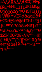
With that in mind, glyph bitmaps are cached to a texture atlas. The image below shows a texture atlas with glyph bitmaps of ASCII characters.
The glyph for the symbol * requires less space than the glyph for the symbol A, how big should the texture atlas be to fit all required glyphs?
A glyph bitmap can be viewed as a rectangle. I allocated it for the worst case scenario by taking the maximum dimensions of all rectangles multiplied by their total count.
Fun fact, rectangle packing is an NP-hard problem, see also Exploring rectangle packing algorithms.
Text shaping
The glyphs are now on the GPU, and the string REal SHader EDitor can be rendered by sampling the corresponding bitmaps out of the texture atlas.
Well, as long as the used font file is monospaced and there is a one-to-one mapping between characters and glyphs.
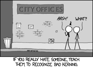
Otherwise, there might be some issues with kerning, and when dealing with Unicode text multiple characters could be combined into a single glyph.
We can use the HarfBuzz library to convert a sequence of Unicode characters into a sequence of glyphs. Then we can render this new sequence of glyphs.

Although it would be weird to use a non-monospaced font for a shader file editor, I wanted to support it for completeness and correctness.
That’s it! Well, Unicode text isn’t the only place where multiple characters can be combined into a single glyph.
A font can also define ligatures, very commonly seen with fl or fi letter combinations.
Hint, float contains an fl combination.
The previously mentioned texture atlas doesn’t contain this glyph bitmap, as it isn’t mapped to either the f or the l character.
I didn’t handle this case yet. The texture atlas should be dynamically updated with the needed glyphs that are visible on the screen.
Generating the quads for rendering
Now we know where and which glyphs need to be rendered, we can generate a list of vertices for the GPU to render the glyphs.
A series of quad vertices is generated for each glyph. The image below shows the generated geometry for the REal SHader EDitor string.

Each vertex of the quad is defined with its position on the screen, the texture coordinates in the texture atlas and the color. A quad can be represented with 6 vertices, or 4 vertices and 6 indices when using indexed drawing.
struct [[nodiscard]] vertex_t final
{
    glm::vec2 position;
    glm::vec2 uv;
    glm::vec4 color;
};
There is a bit of an overhead here though, the color attribute is repeated in each vertex and the geometry always consists of quads, would be great if they could be generated on the graphics card. First, we’ll extend the vertex definition to contain the size of the rectangle.
struct [[nodiscard]] vertex_t final
{
    glm::vec2 position;
    glm::vec2 size;
    glm::vec2 uv;
    glm::vec4 color;
};
Instead of generating vertices for all four corners of the rectangle, we generate only the top left corner vertex. Then we’ll use the tesselation shaders to generate the rest on the GPU.
The vertex shader forwards the data from the vertex input to the tesselation control shader. The input to the control shader is a group of vertices size of a patch, in this case, the patch size is 1, the top left corner.
layout(location = 0) in vec2 inSize[];
layout(location = 1) in vec2 inTexCoords[];
layout(location = 2) in vec4 inColor[];

layout(vertices = 1) out;

layout(location = 0) out vec2 outSize[];
layout(location = 1) out vec2 outTexCoords[];
layout(location = 2) out vec4 outColor[];
Tesselation control shader outputs a new set of vertices how much new geometry will be generated. In this case, the output is still one vertex, and the attribute values are also just forwarded.
void main(void)
{
    if (gl_InvocationID == 0)
    {
        gl_TessLevelOuter[0] = 1.0;
        gl_TessLevelOuter[1] = 1.0;
        gl_TessLevelOuter[2] = 1.0;
        gl_TessLevelOuter[3] = 1.0;

        gl_TessLevelInner[0] = 1.0;
        gl_TessLevelInner[1] = 1.0;
    }

    gl_out[gl_InvocationID].gl_Position = gl_in[gl_InvocationID].gl_Position;
    outSize[gl_InvocationID] = inSize[gl_InvocationID];
    outTexCoords[gl_InvocationID] = inTexCoords[gl_InvocationID];
    outColor[gl_InvocationID] = inColor[gl_InvocationID];
}
Now, we need the inputs and outputs of the tesselation evaluation shader:
layout(quads, equal_spacing, ccw) in;

layout(location = 0) in vec2 inSize[];
layout(location = 1) in vec2 inTexCoords[];
layout(location = 2) in vec4 inColor[];

layout(push_constant) uniform PushConst { mat4 projection; } pc;

layout(location = 0) out vec2 outTexCoords;
layout(location = 1) out vec4 outTexColor;
It defines how many vertices will be generated by the tesselation primitive generator that is executed between the control and evaluation shaders: layout(quads, equal_spacing, ccw) in;.
The tesselation evaluation shader is invoked with the output of the control shader and the generated vertices, and with the builtin gl_TessCoord variable final vertex positions of the quads and texture atlas coordinates can be calculated.
void main(void)
{
    vec2 newPosition = gl_in[0].gl_Position.xy;
    newPosition.x += inSize[0].x - gl_TessCoord.x * inSize[0].x;
    newPosition.y -= gl_TessCoord.y * inSize[0].y;

    gl_Position = pc.projection * vec4(newPosition, 0.0, 1.0);

    outTexCoords = inTexCoords[0] + (inSize[0] - gl_TessCoord.xy * inSize[0]);
    outTexColor = inColor[0];
}
The output of the tesselation evaluation shader is passed to the fragment shader in the usual way, the same as it would have been if only the vertex shader was used.
This is of course completely optional. I’ve done it now only because I wanted to learn how the tesselation shaders work.
Syntax highlighting
With the text now on the screen, we can do something useful. I’ve used the Tree-sitter library to build a syntax tree out of the shader code.
tree_ = ngntxt::parse(parser_,
    tree_,
    [this]([[maybe_unused]] size_t byte,
        size_t row,
        size_t column) -> std::string_view
    { return buffer_.line(row, true).substr(column); });
The syntax trees can be queried for some properties. Tree-sitter grammars define a set of queries that can be used for syntax highlighting. An example of a query that matches GLSL builtin variables in the syntax tree:
((identifier) @variable.builtin
  (#lua-match? @variable.builtin "^gl_"))
Using the result of the query we can assign a different value for the color attribute depending on the node type.
There is a small issue, Tree-sitter works on our original character sequence and the result of the queries returns positions in that sequence. This sequence was changed when we did the text shaping process and they don’t have a one-to-one mapping, so the indices from the syntax tree can’t be used directly.
Luckily HarfBuzz does have a concept of cluster values and we can use that to translate between the rendered glyphs and the original text.
The example below shows cluster values before and after shaping the text, in the case where Eal and ito sequences would have been combined.
R  E  a  l  S  H  a  d  e  r  E  D  i  t  o  r
1  2  3  4  5  6  7  8  9 10 11 12 13 14 15 16

R  Eal  S  H  a  d  e  r  E  D  ito  r
1    2  5  6  7  8  9 10 11 12   13 16
Final words
If you are still not convinced that text hates us, you can continue reading these articles Text Rendering Hates You and Text Editing Hates You Too. Adventures in Text Rendering: Kerning and Glyph Atlases is also a nice article.
The editor is in a far from usable state, it renders the whole file at once even the parts of the text that aren’t visible on the screen.
I’m also a bit bothered that the whole state is stored in a single std::string object.
It should probably support saving and opening files, that’s likely a requirement.
For any questions or corrections to this post, leave a comment in discussion thread on GitHub or any other place where you see this.
Diff compared to the state shown in the previous post.
Previous posts in the series:
- The Invisibles
- Finding the Way Home
- Navigating Bad Assumptions
- Eppur si muove
- Sidequests And Loose Ends