Rendering Medvednica From a Heightmap
by Jan Kelemen
Na Sljeme, na Sljeme na Sljeme…. I started this project to explore the usage of Bullet’s btHeightfieldTerrainShape collision shape, initial idea was to generate a heightmap using Perlin noise. I ended up using a static heightmap as I didn’t like the results I was getting with the terrain generated from using plain noise.
Results are in the video below, Link to the source code: jan-kelemen/soil
Heightmaps
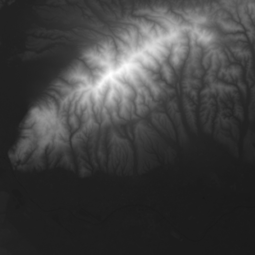
Heightmaps are images that are used to represent the height of a terrain. Values taken from this image are mapped to a rectangular grid, combining these two things gives us a coordinate in 3D space. Brighter values represent a higher point in the space. Below is the image I’ve used for this project, although you can generate a heightmap for any point of Earth with a site like manticorp.github.io/unrealheightmap.
For simplicity, my code supports rectangular images where the dimension of the image is a 2^n + 1, more on that later.
To get some color onto the terrain, I decided to generate the colors based on terrain heights. The terrain below a height value of 50 is colored with green color, while the terrain above has a color that is linearly interpolated between green and white. White becomes more dominant as the height increases. Additionally, some Perlin noise is added in the color mixing of the linearly interpolated area and on individual terrain quads. Finally, ambient and diffuse lighting model is applied in the fragment shader with a static light source located above the center of the terrain.
The noise map image is generated at the program’s start, and it looks like the example below.

Another approach to texturing the terrain would be to use a color texture, similar to the principle of the heightmap, but the image would contain the color of the point in the world. While this would be significantly less computationally expensive, I discovered that the texture would have to be very detailed to work at this scale.
Level of detail
The original image I used has dimensions 1025x1025, which ends up being 1050625 vertices. Modern graphics cards can handle vertex counts like this without many issues, but it could cause performance issues on less capable hardware like integrated graphics cards. Also to be considered is the fact that in general, the terrain isn’t the only thing being rendered and that it wouldn’t make any sense to render something close to the player with the same level of detail as something in the distance.
The “simplest” approach to this is to reduce the number of vertices being rendered. The terrain is split up into chunks with dimensions 65x65, this is the reason why there is a limitation on the used heightmap sizes. For this chunk size, 7 LOD meshes are generated. At level 0 which is the most detailed, every vertex is rendered, at level 1 every second vertex is rendered, effectively becoming a 33x33 mesh. The lowest level 6, is a 2x2 mesh which renders only corners of the chunk. Check the video at timestamp 00:36 for a demonstration of changing LOD levels.
This algorithm is very naive, there are better ones like geomipmapping. One particular problem from which it suffers is that it causes tears in the terrain when chunks with different LODs are located next to each other.
Physics chunks
For the chunks along the diagonal of the image, the collision shape is loaded. In the previous post I went over the collision shapes supported by Bullet physics, btHeightfieldTerrainShape was one that I didn’t use there.
Computationally this collision shape stands between btConvexHullShape and btGImpactMeshShape.
For a terrain chunk, the collision shape is defined based on the heightmap values. At timestamp 01:00 in the video, you can see the debug view of the loaded collision objects.
These are rendered with Bullet’s debug renderer functionality, for it I had to implement btIDebugDraw interface.
I was kind of expecting that synchronizing the graphical representation of the world and the physics simulation would be tricky, so this was one of the first things I’ve done on this project.
It isn’t too hard to implement either, at minimum, only the implementation of drawLine method is needed.
In the general case these meshes would be loaded for the chunks that are close to the player, also loading them with a full level of detail is probably a bit too much. Drawing the debug view of these meshes is more time consuming than the rest of the terrain, I’ll have to do some more research on how to improve the performance on this.
Improvements to the rendering engine
The engine now has a name, it’s niku! It’s named after Nikumaroro an island where you get lost and no one searches for you. While there is no immediate plan to extract it to a dedicated repository for it yet, I’ll do it at one point in the future. Currently, it’s still too volatile and changes a lot between projects.
Image mipmapping
At one point I tried using a texture image for texturing the terrain, this was still when I used meshes generated from the Perlin noise. I noticed that the rendering of the mesh takes a bit too long as I increase the mesh size, going from a 25x25 to a 100x100 mesh would result in a significant FPS drop. Thanks to the help of people at Vulkan Discord and NVIDIA Nsight Graphics profiler, the result was that the fragment shader spends a lot of time loading textures.
This led to adding support for image mipmapping, which is a process of generating downscaled versions of an image, think of it as LOD for images. Generating mips is explained in the Vulkan Tutorial - Generating Mipmaps. I mostly adapted the code from there, and it resolved the problem I had. In fact, after generating the mips, the hotspot for the scene render was math being performed in the vertex shader, instead of texture loading in the fragment shader.
Below is a mipped image of a noise map image shown previously. Now reduced to 64x64 dimensions instead of the original 1025x1025.

Camera controller
Finally found a pattern for organizing the camera code which I like. The key was to split the handling of user input from the math representation. The code for camera handling is now split into two parts.
The base class niku::camera allows for implementation of different camera types, currently, the only implementation is niku::perspective_camera which calculates view and projection matrices.
This inheritance tree can be extended with an orthographic camera for example.
The other part is a camera controller which is responsible for handling user input like moving the camera with the mouse or the keyboard.
Currently, the implementation of this is soil::free_camera_controller which allows moving anywhere in the world, an alternative implementation would be a follow camera which tracks behind a player character.
Multiple render passes
Previously the rendering code implied that the whole render of the scene would be done in a single render pass.
Now the application receives a primary command buffer from the rendering backend in which it can start its render passes, using the helper vkrndr::render_pass.
vkrndr::render_pass render_pass;

render_pass.with_color_attachment(VK_ATTACHMENT_LOAD_OP_LOAD,
    VK_ATTACHMENT_STORE_OP_STORE,
    target_image,
    std::nullopt, // Clear color not used when only loading attachments
    color_image_->view);
render_pass.with_depth_attachment(VK_ATTACHMENT_LOAD_OP_CLEAR,
    VK_ATTACHMENT_STORE_OP_STORE,
    depth_buffer_->view,
    VkClearValue{.depthStencil = {1.0f, 0}});

auto guard{render_pass.begin(command_buffer, render_area)};
In this project, rendering consists of three render passes. The first render pass renders the terrain updating the color and depth attachments. The second render pass is used for the Bullet’s debug view which updates the color attachment and uses the depth attachment but doesn’t update it. The third render pass is used for ImGui windows drawn on top of everything which uses only the color attachment.
Other news
cpp-starter-template has gotten a toolchain update.
Most of my projects are in one way or another generated from this template, I’ve updated it to support GCC-14 both for x86_64 and for AArch64 architectures.
Also, the GitHub Actions runners were updated to new ubuntu-24.04 runners.
There’s more stuff for which I want to add support there, like clang-cl frontend on Windows and support for libc++ when compiling with Clang on Linux, when there’s time for that…
Final words
This approach to terrain rendering shown here is far from a complete one. Important things that are missing are frustum culling and dynamic level of detail. I’ll explore those at a later point in time. The rendering engine also requires more work, along with the stuff I mentioned in the previous post, I would like to improve on the command pool and descriptor pool handling. Currently, the required allocations for descriptor pools are hardcoded in the rendering engine, specifying these quantities should be moved into the application. I’m considering trying out SPIRV-Reflect to generate the descriptor requirements dynamically from the loaded shaders.
For any questions or corrections to this post, contact me via email at jkeleme@gmail.com.
Previous posts in the series:
tags: C++ - Vulkan - graphics programming - bullet3 physics - niku