Chess engine visualization
by Jan Kelemen
In the previous post Remaking World 1-1 with Vulkan, mostly I’ve shown my progress with learning graphics programming. In the meantime, I finished another project pawn, a UCI protocol “compatible” GUI rendered with Vulkan API. Link to the source code: jan-kelemen/pawn.
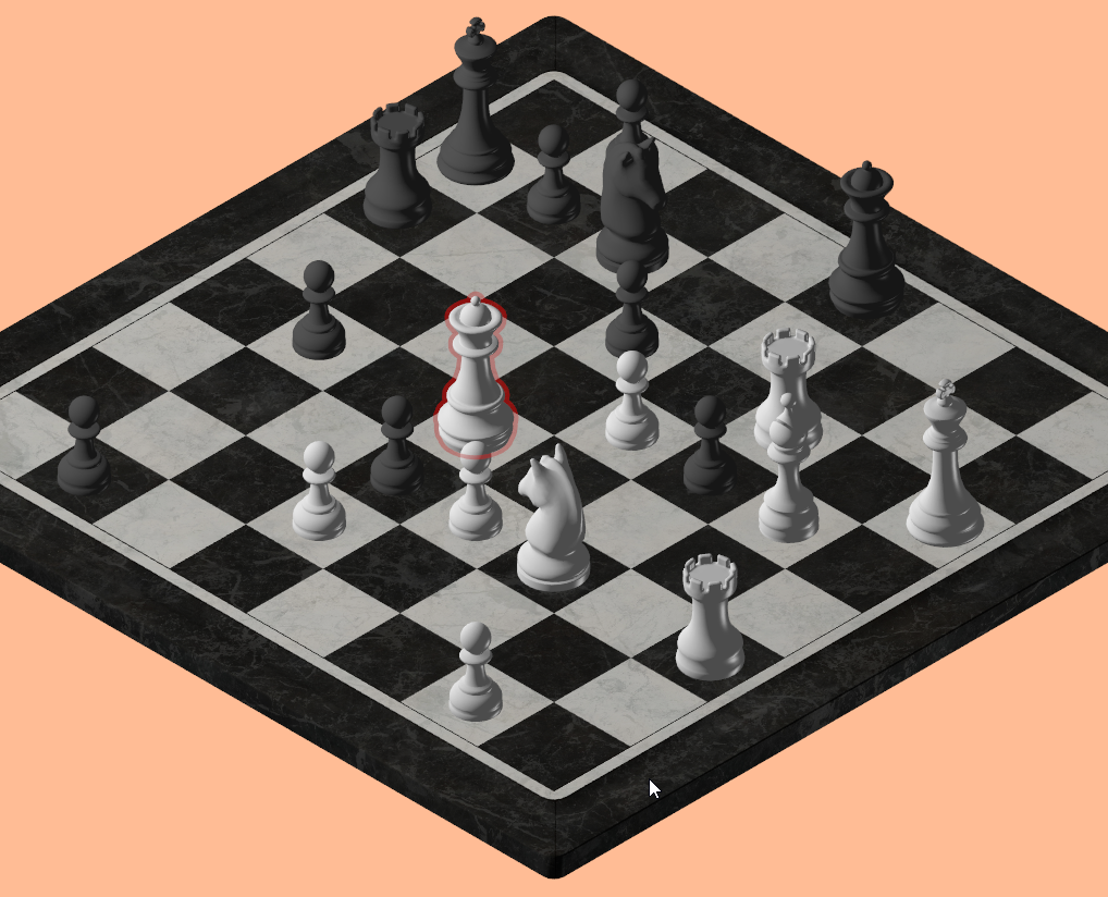
The original idea that I had in mind when I started was to allow the player to play against the chess engine and for the board to be rendered in an isometric projection and 2.5D, kind of like IsoChess. This changed a bit along the way, I’ve kept the isometric view of the board, but the pieces and the board are full 3D models, it turns out it’s easier to find 3D models than the ones that would fit into the 2.5D style. The second difference is that the player doesn’t exist, the chess engine plays against itself, I’ll explain the reasons for this later.
Communication with the chess engine
Visualization program and the chess engine communicate over a text based Universal Chess Interface protocol. Although I have used only Stockfish for testing it should be possible to use another chess engine that supports the UCI protocol. The visualization is started by launching the pawn executable and forwarding the path to the chess engine executable, which is then started automatically from the visualization program, for example:
pawn.exe "stockfish-windows-x86-64-bmi2\stockfish\stockfish-windows-x86-64-bmi2.exe"
The chess engine is started as a child process using the Boost.Process library. As mentioned UCI protocol is text based, so it’s easy to parse with a parser combinator, for this, I’ve used Boost.Spirit.X3.
An example of UCI based communication, noting the key commands sent between visualization and the engine (> marks requests to the engine while < symbol marks responses):
> uci
< uciok
> position startpos
> go movetime 1000
< bestmove e2e4 ponder c7c5
> position startpos moves e2e4
> go movetime 1000
< bestmove c7c5 ponder g1f3
In general, I would have picked foonathan/lexy for the parser combinator, from my experience I’ve found it to have clearer error messages and a bit more user friendly, but I’ve decided on Spirit.X3 since I already had Boost as a dependency.
The reason why “compatible” is under quotation marks is the fact that I’ve implemented a minimal set of commands required to play one game of chess.
Loading the glTF model
glTF is a standardized graphics asset interchange format. While the specification of this format is extensive, in this project I’ve used only a small subset of supported features. I only needed to load vertex meshes along with the surface normals and the textures from the model for visualizing the chess game. For this I’ve chosen to use TinyGLTF library and Sascha Willems’ Vulkan physically-Based Renderer as an reference implementation.
The model that I’m using is Riley Queen’s Chess Set hosted on Poly Haven, thanks for making it free to use!
A lesson on why being explicit is good
My previous rendering code was capable of rendering 2D graphics and textures, to render the 3D geometry correctly I’ve had to extend it with support for depth testing. One part of setting up the isometric projection is the orthographic perspective matrix, for this I’ve used glm::ortho, which along with other parameters, takes in near and far planes of the frustum.
glm::mat4 glm::ortho(float left, float right, float bottom, float top, float zNear, float zFar);
These are mapped to the depth coordinates of the rendering API, in Vulkan, the default depth is in range [0.0, 1.0]. GLM on the other hand was built for OpenGL by default which uses the depth range of [-1.0, 1.0] to change the default behavior one can define a preprocessor macro and use the other range.
Well, I was missing before one of my includes of GLM library, which led to it using the depth range [-1.0, 1.0], lots of hours wasted looking at vertex shader output in RenderDoc. So now I use the function which explicitly handles coordinate space required for Vulkan:
glm::fmat4 pawn::orthographic_camera::projection_matrix() const
{
    // https://computergraphics.stackexchange.com/a/13809
    return glm::orthoRH_ZO(position_.x - projection_[0],
        position_.x + projection_[0],
        position_.y - projection_[0],
        position_.y + projection_[0],
        near_plane(),
        far_plane());
}
Vulkan synchronization validation
Vulkan validation layers are great, though as I have learned, synchronization validation isn’t enabled by default. While I didn’t have any visible synchronization issues I decided to turn them on anyway.
constexpr std::array const validation_feature_enable{
    VK_VALIDATION_FEATURE_ENABLE_SYNCHRONIZATION_VALIDATION_EXT};

constexpr VkValidationFeaturesEXT validation_features = {
    VK_STRUCTURE_TYPE_VALIDATION_FEATURES_EXT,
    nullptr,
    vkrndr::count_cast(validation_feature_enable.size()),
    validation_feature_enable.data(),
    0,
    nullptr};
I had no new error messages after enabling them, or so I thought. After checking how things are working on Linux I’ve gotten new error messages about a write hazard. Turns out my image transitions from color attachment to present layout weren’t correct, maybe this would have shown up as an error sometime later, I didn’t observe any visual glitches while working on this project. Still shows the importance of writing cross platform code and testing on different devices as the driver implementation and validation can vary across devices and platforms.
Visualizing the chess pieces
The chess pieces are rendered in a flat color, either white or black, and no texure is applied to them, while the board mesh is with a texture. Fragment shader applies a lighting model to the pieces and the board so that the pieces don’t look flat. To avoid switching between the shaders for the board and the pieces, I’m using the same shader and control if the texture needs to be used via push constants between draw calls.
To indicate which piece was last moved, a red outline is drawn around it. This also requires a separate shader, so before updating the scene I partition the geometry based on the highlight state.
std::stable_partition(draw_meshes_.begin(),
    std::next(draw_meshes_.begin(), used_pieces_),
    [](auto const& piece) { return !piece.highlighted; });
This makes it so that the highlighted piece is always drawn last and that the graphics pipelines are switched only once during the drawing of the scene.

Phong lighting model
This lighting model consists of three components: ambient, diffuse and specular. The implementation required for this is done almost exclusively in the shaders, the only things required from the application are the light color, light position and surface normals that are loaded from the glTF model. I’ve followed the LearnOpenGL’s Basic Lighting which I was able to use almost without changes. For the black and white pieces I use the same vertices and normals, the black pieces are just rotated by 180 degrees around the Y axis, at one point I forgot to apply this rotation to the normals, which led to shading being on the incorrect side of the piece.
Shader storage buffers
The pieces are positioned on the board using the model transformation matrix. There are various ways how this could have been passed to the shader, this time I decided on using shader storage buffers. Which can be dynamic in size as opposed to uniform buffers, this was convenient as the number of pieces on the board varies. The buffer is however allocated at a fixed size and just some parts of it are used by the vertex shader. Push constants are used to transfer the correct index which needs to be used for the currently drawn piece.
struct Transform {
    mat4 model;
    mat4 view;
    mat4 projection;
};

layout(std140, binding = 0) readonly buffer TransformBuffer {
    Transform transforms[];
} transformBuffer;
Object outlining using the stencil buffer
After everything but the highlighted piece is rendered the pipeline is switched to the one which writes to the stencil buffer. This creates a “hole” in the stencil which is slightly enlarged in comparison to the original vertex geometry of the piece which is colored in red and given some transparency using alpha blending. Below is a stencil example of a frame in which the black knight was highlighted.

Changes to ImGui integration
In my previous post, I’ve shown that ImGui only requires a small descriptor pool to be rendered with a custom renderer. This is still the case, but the render pass in which it is drawn also must be compatible. Since I’ve added the depth and stencil tests to my main scene, this made the render pass incompatible with the one ImGui requires which only has a color attachment. Therefore I’ve decided to split the ImGui rendering completely into a separate command buffer with its own dedicated render pass.
Final words
So why isn’t there a possibility to play against the chess engine? In the tiled isometric projection calculating from screen space to world space is a fairly straightforward mathematical formula. In the 3D world things are a bit more complicated than that. The basic step is to get a ray direction by using glm::unProject and then intersecting it with a bounding box of the object. There is also a possibility of color coding the piece identifier into the stencil buffer or a separate color image. Since I’ve already used the stencil buffer for the outline and I didn’t want to rerender the whole scene just to get the identity of the piece under the cursor, ultimately I decided to study object picking on a future project.
For any questions or corrections to this post, contact me via email at jkeleme@gmail.com.
tags: C++ - Vulkan - ImGui - graphics programming - chess